Showing posts with label RV. Show all posts

Thursday, June 24, 2021

Truck Camper Electrical System Upgrade


This entire project started because the AGM batteries in our 2014 Arctic Fox 1150 were 7 years old and were getting pretty tired.  We decided to switch to lithium batteries and discovered that neither the Zamp solar controller or the Progressive Converter/Charger we had would support lithium.  Since we needed to replace them, we decided to go a step further and install an inverter/charger to provide 120V power without being plugged in or running a generator.  We also wanted to be able to keep the batteries charged without having to carry a generator.  That resulted in upgrading to an MPPT solar controller and the addition of a DC/DC charger to the system which will connect to a heavier 2 AWG wire running from the truck alternator via an SB175 Anderson Connector.

Victron Multiplus
12V 2000 watt inverter/charger

Once we made the decision to upgrade and add all these components, we started by tracing the existing wiring. We had previously removed the plywood from the bottom of the camper and having access to the underside made this, not easy, but at least easier than it could have been. 

After learning the existing wiring, we were able to determine what wire we could remove and what wire to leave as it could be reused in the new system.  The next step was to decide on which components to purchase and to figure out where they would all get installed.  We ended up with Battleborn heated batteries and Victron components: a Multiplus Compact 12/2000 watt inverter; a VE-Bus Smart Dongle (provides Bluetooth for the inverter); a SmartSolar MPPT 100/30 solar controller; an Orion-TR Smart 12/12V 30A isolated DC/DC charger; a BMV-712 battery monitor; a Lynx Distributor; two 250A BlueSea bus bars; a BlueSea PowerPost; and 3 BlueSea Maxi fuse blocks.  Selecting the components was fairly easy - finding a spot to put them was significantly more challenging.  

The battery box in our TC would fit 2 of the Battleborns, but since we were adding an inverter, we knew we would be using more power and wanted to add an additional battery.  We do not have an onboard generator, so the generator compartment became the new battery box.   In order to make room for everything, we stripped almost everything out of the generator compartment.  That meant removing the 120V wiring and connection box, the 2 AWG DC wiring that ran to the old battery compartment, and the gas line that ran down to the gas outlet under the bumper (which we had never used).

Wiring and gas line
before removal


Generator compartment with contents removed


The inverter was probably the most challenging to find a spot for since it was the largest component.  We decided to install it where the sliding tray used to be.  We had removed the tray several years ago because it jammed every time we used it despite many attempts to fix it.  With the bottom off the camper, we were able to remove the track for the tray as well.  We cut a board to fit the bottom of the compartment that provided a level surface and a solid attachment spot for the inverter.

Sliding tray and track removed
New support board installed

The remainder of the components were installed in the front of the camper.  We removed the old charger/converter from under the step to the bed and the 6 AWG wire that was connected to it.  We removed the transfer switch from under the kitchen sink being careful to label the wires as we disconnected them so we would know what was what later.  We also removed the Zamp solar controller and connected the input to the output wires so they were long enough to reach the new controller.

Under step to bed with original converter/charger


Once we were sure we had the space to install all the components we wanted, we worked with Battleborn to properly design how everything needed to go together.  They were very responsive in reviewing our proposed design and helping us determine what gauge wire was needed and where fuses should be installed.  They were great about answering any questions we had as we went through the install.  We made a few tweaks as we went along and ended up with a system that looks like this:


Once we had everything, it was time to start installing the components.  The battery disconnect switch, the shunt for the Victron BMV712 battery monitor, and the Victron Lynx Distributor were attached to the rear wall of the old generator compartment (the new battery compartment). We mounted a piece of 3/4" plywood along the back to give the components something solid to attach to.  We also made a board to sit under the batteries that would help hold them in position and provide a place to strap them down.  We found the bottom of the generator compartment was quite thin so we decided to use caulk to glue the board down rather than relying on screws alone. We cut some additional holes though the left hand wall to allow us to run cables to the inverter and forward to the rest of the components. 

Components installed in generator compartment

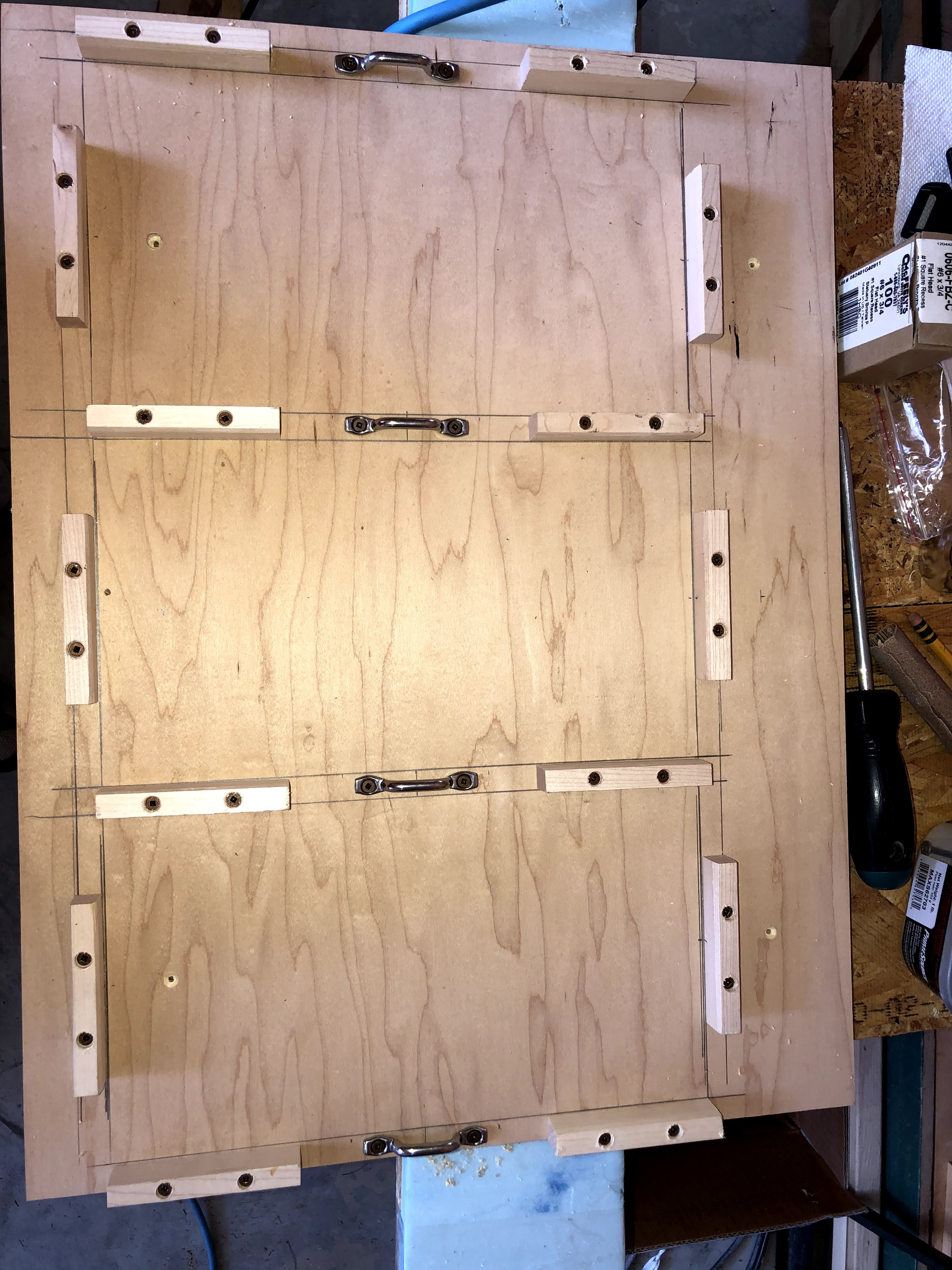
Battery board with footman loops installed
Battery straps fitted and installed


The new solar controller was installed under the kitchen sink immediately below the controller for the Reico-Titan jacks.  Just below the solar controller we put an electrical connection box where we added new wire to the shore power and the AC fuse panel wires that used to run to the transfer switch.  The wire from shore power goes to AC In on the inverter and the wire to the fuse panel comes from AC Out.


The DC/DC charger was installed under the step to the bed in the spot that used to hold the converter/charger.  Like we did in the generator compartment, we mounted a piece of 3/4" plywood along the front wall under the step.  We attached the positive and negative bus bars as well as the fuse blocks to the plywood.

Components installed under step

Once we had the components in place, we were able to cut the wires and crimp on the lugs.  The wires running from the batteries to the Lynx Distributor and from the Lynx to the inverter are 2/0.

Inverter Installed
We put cable sleeves around the cables to protect
them from the edge of the inverter case.

Battery installation completed


The wires running from the Lynx Distributor forward to the front bus bars are the 2 AWG cables that previously ran from the generator compartment to the old battery box.  The input wires for the solar controller are the original 10 AWG from Northwood, the outputs to the bus bars are new 6 AWG.  The existing 6 AWG wires that previously ran from the batteries are now connected to the front bus bars and supply power to the DC fuse panel.  

Wiring under step completed


For input to the DC/DC controller, we ran 2 AWG out under the kitchen counter (between the old battery box and the water heater) to an Anderson connector on the front edge of the camper.  We found that the max wire size for the DC/DC charger is 6 AWG.  Since we wanted to run 2 AWG out to the Anderson connector, we added a Power Post that we used to connect the black 2 AWG and a short segment of 6 AWG to connect to the charger.  The red wire ran through a fuse block so we were able to convert from 2 AWG to 6 AWG that way.  The output from the DC/DC charger to the bus bars is new 6 AWG.

Wire run out between the battery
box (on left)and the water heater

Wire gable for 2 AWG wires 


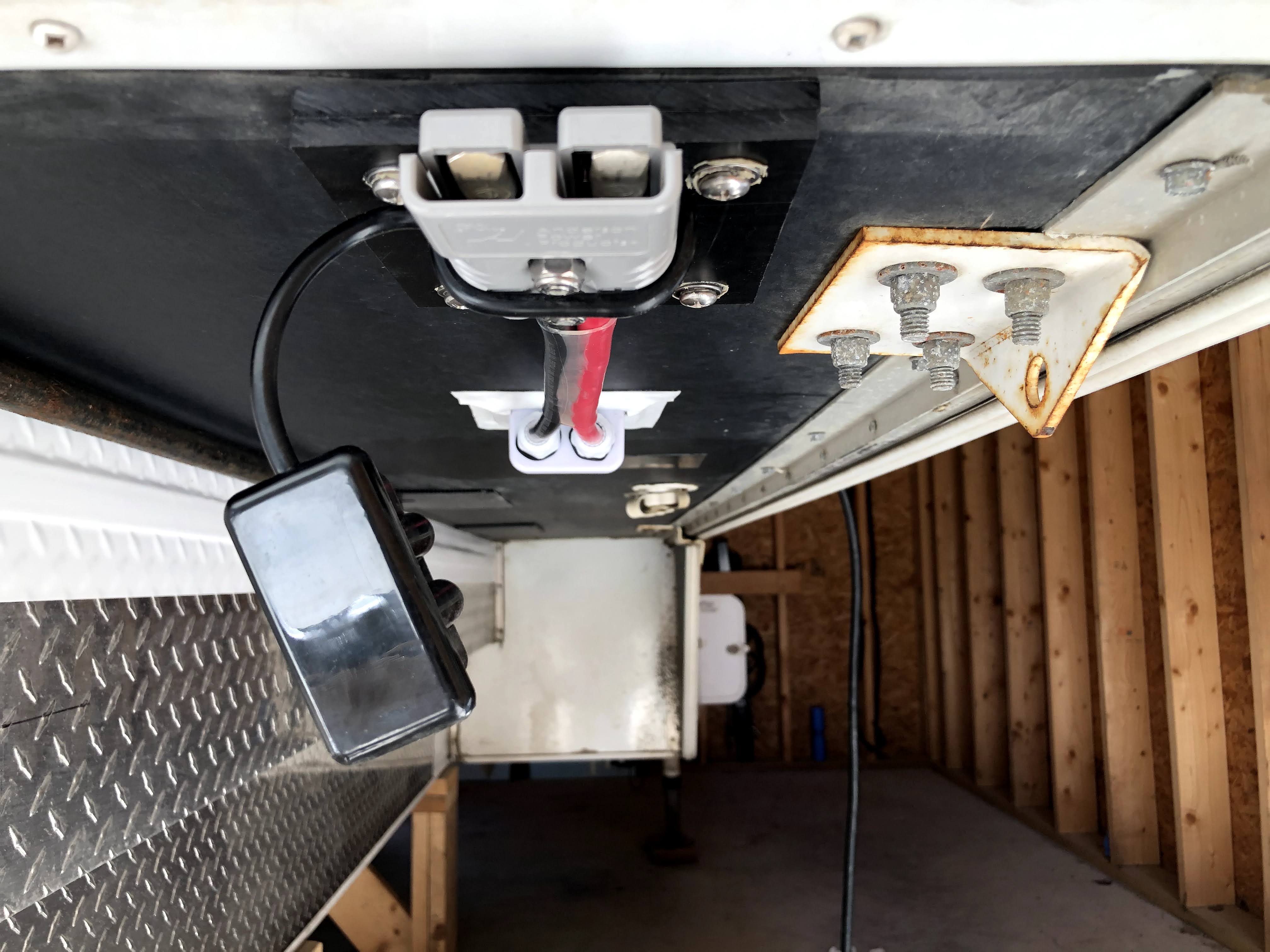
Front view of Anderson connector  
The thing hanging down is a dust cover


We installed the BMV 712 Battery Monitor in the side of the kitchen sink cabinet along with the switch for the battery heaters.  The Battleborn heated batteries have a temp control that will only turn on the heater if the internal battery temperature reaches 35F.  However they also provide a switch which allows us to turn off the heat feature completely when we are traveling in the summer.


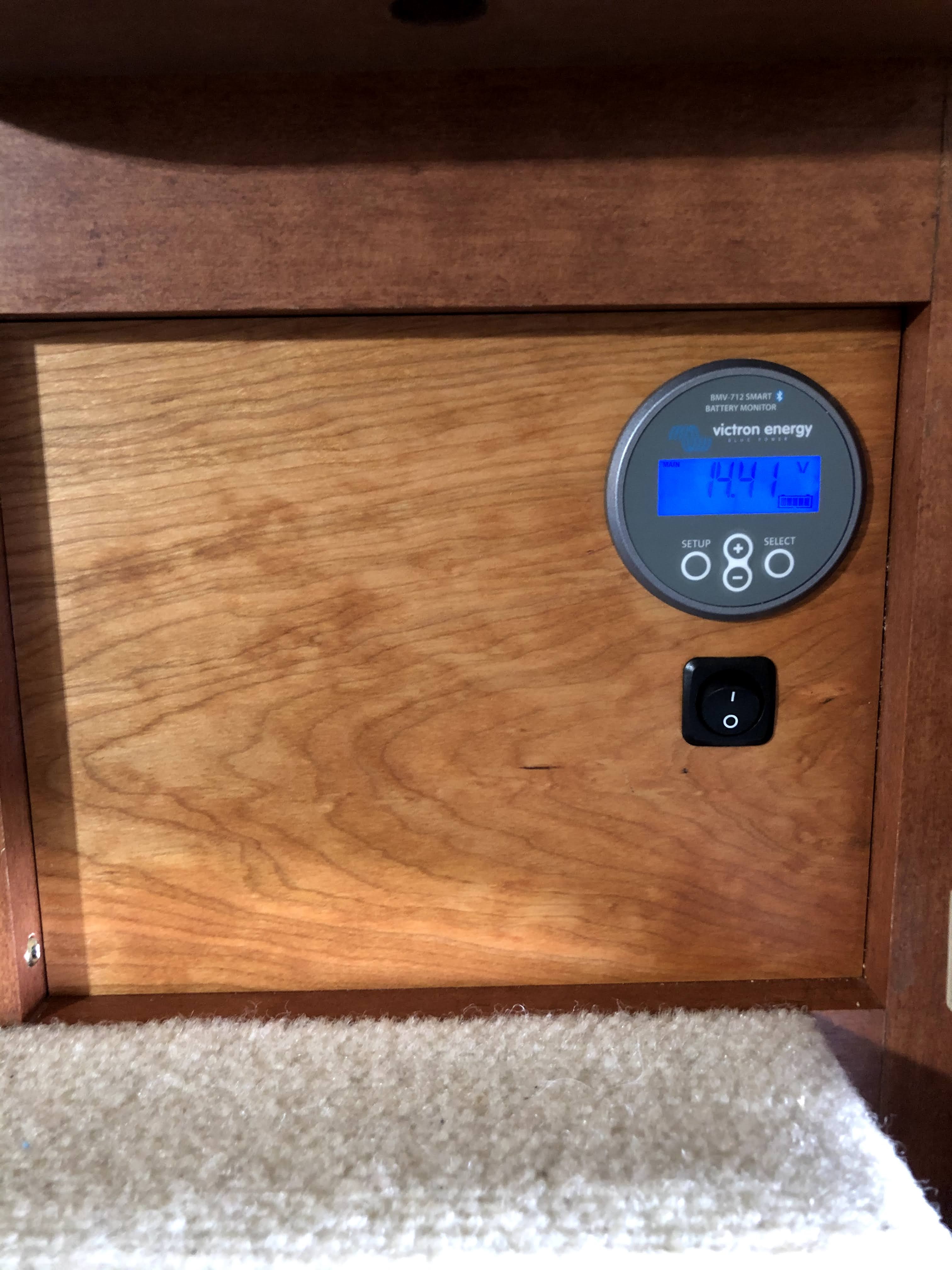
New wooden cover for location of the old solar controller


For those considering tackling a project like this on your own, one thing to think about is whether you have the necessary tools.  We thought we were fairly well equipped, but found that there were several tools needed that we did not have. Who knew there were so many different types of crimpers?  

We ended up making a bit of a mistake when purchasing an indent crimper for creating the heavier cables and later realizing that same crimper would not work for crimping the Anderson connectors.  We originally purchased a TH1818 crimper from TEMCo and should have purchased the TH0006 instead as it would have been able to crimp both the cables and the Anderson connectors.  That said, we found the TH1818 indent crimper easier to use, so if you don't need to crimp Anderson connectors, then I would suggest going that route.  We purchased directly from TEMCo.  Their prices were better than Amazon and shipping was free and fairly efficient.

We purchased a crimper and ferrules from Ferrules Direct.  Ferrules made inserting wires into the solar controller and the DC/DC charger so much easier than trying to insert and make a good connection with bare wire.

We also purchased a crimper for MC4 connectors.  Our previous solar controller was from Zamp which required the solar panels to be connected in parallel.  Our new controller is MPPT which does better with the panels connected in series.  We rewired the panels using MC4 connectors so they can easily be changed from series to parallel connections if we ever need to.

The wire, lugs, and Anderson connectors we purchased from Battery Cables USA.  We used their extreme battery cable which is amazingly flexible considering it is dual jacketed.  They ship stuff really quickly and inexpensively ($3.97 flat rate shipping, no matter how much stuff you buy).  

We spent more time designing and planning (and waiting for Fed Ex and UPS) than we did actually installing components.  We have done lots of AC wiring, but did not have much experience with DC wiring, especially with the larger gauge wires needed on a system like this.  We tried to test fit everything before drilling, screwing or cutting.  Overall, I would say that the project went pretty well.  We only made a couple of relatively small mistakes that we were able to fix without too much hassle.  

We have tested the system while sitting in the driveway, and are quite pleased with the way everything is working.  The bluetooth enabled Victron components and the Victron Connect app work very well. It is awesome to be able to monitor and change settings on all the components from our phones.  We are very much looking forward to getting out camping and giving the system a real test.


Saturday, August 29, 2020

Installing a Cold Weather Kit on our Norcold Refrigerator

A couple of years ago we were camping during a cold and snowy weekend.  Overnight lows were in the single digits ºF and we discovered that our refrigerator did not work when the weather was that cold.  After a bit of research we found this was a common enough problem that Norcold makes a cold weather kit to correct it.  I believe this kit is now standard, but that was not the case in our 2014 Arctic Fox 1150.  Since we are mostly stuck at home because of the pandemic, we decided to take this opportunity to order and install the kit.  The kit can be found at Amazon, the model number is 634913.  This kit fits 6, 8, 10, 12, 17, and 18 cu ft gas absorption model refrigerators.


Before we could install the kit, we needed to get access to the back of the refrigerator.  We removed the lower refrigerator vent panel on the outside of the camper and found that we could not access the parts needed without moving the refrigerator forward.  We did not find any information about how to remove a refrigerator from an Arctic Fox TC. That is one of the primary motivations for this blog post.  Since we had to figure it out, we thought it might be helpful to others to know what we did.   

We started by turning off the propane, disconnected from shore power and flipped the red battery disconnect (which is in the rear compartment with the dump tank valves in our 1150).   

We then removed the freezer and refrigerator doors so we would have access to the inside attachment points.  There are two screws at the top of the refrigerator that need to be removed.  First remove the plastic caps and then remove the screws.  


Removing those screws will also release the trim that sits across the top of the freezer.


There are multiple screws at the bottom of the refrigerator that need to be removed.  Remove the two screws across the bottom as well as the lower hinge.  This will allow you to remove the lower trim.


Once the lower trim is removed, there are two additional screws that need to be removed.


Once all the internal screws are removed, it is time to move to the outside of the camper.  

We unplugged the 12 V connections and the AC power cord.  We used a VOM to validate that there was no power to the 12 V wires.


We removed the clamp holding the AC power cord just above the outlet.

Next we disconnected the propane.  We used two wrenches, one to loosen the connection and one to prevent anything else from twisting.


Then we removed the attachment screws.  In ours case there are 5 of them, but it appears to be a bit random, so your mileage may vary.


Note there was sealant around the base of the gas line and on top of each of the attachment screws that we needed to remove.  We also found that the stabilizing clamp at the base of the gas line needed to be loosened as it was pinching the metal on the fridge.   

Once all the attachment points were disconnected, we were able to move the refrigerator forward to give us room to work.  There wasn't a good way to get leverage to move it, but we found that by having one person inside the camper pulling and one outside pushing, we were able to move it enough.

The installation instructions for this cold weather kit are really awful.  We read them over several times before figuring out how to approach it.  My recommendation is to ignore step 3 and the associated diagram as it confused more than it helped. 

The kit contains a blue resistive wire that has adhesive on one side.  It gets attached to the thin refrigerant tube.  There is a section of the tube that runs in a curve horizontally at the top.  The wire gets twisted around that section and then runs along side (but not twisted around) the vertical section below it.  There are two notches along the wired tape.  The instructions were not correct about which notch to use.  It will likely vary by model, so I suggest laying out the wire to see how it will fit before removing the adhesive backing.  We found it easier to remove the backing a bit at a time as we went along, rather than to remove it all at once as directed by the instructions.  


Looking down from above 
Horizontal section from above  


 Horizontal section from below


Once the wire tape was in place, we added wire ties at the ends and at the curved points. We used a few more ties than were supplied with the kit.

The kit includes a temperature sensor which needed to be mounted.  We used a sharpie to mark where the holes needed to be and used a 9/64 bit to drill them.  We then used the spacers and screws provided with the kit to mount it.  


The next step was to connect the heater tape to the 12 volt power supply and ground wires.  The instructions said to cut the 12V supply wires, then solder the heater wire into it.  The problem with that approach is that would hardwire the heater to the 12V power supply and we would not be able to remove the refrigerator without having to cut the wires.  We decided to modify the heater wires by adding a quick connect so that we would be able to disconnect both the heater and refrigerator power should we ever need to remove the fridge in the future.


Once the wires were attached, we were ready to put everything back together.  We pushed the refrigerator back into place.  We decided to reattach all the interior screws first, but I suspect the order doesn't really matter.  We then replaced the 5 outside screws, reconnected the gas line and tightened the screw on the stabilizing clamp, reconnected the 12V power and ground wires, and plugged in the AC power cord and reattached the clamp holding it in place.  We then flipped the battery disconnect switch back, plugged in to shore power and turned the propane back on.  We checked the propane connection behind the fridge for leaks.  Everything was fine, so we ran a test to make sure the fridge still worked.  It was fine on AC power.  The first time we tried it on propane we got an error code, probably because we needed to purge the propane line.  We lit one of the burners on the stove, let it run for a few seconds.  When we tried the fridge again, everything worked correctly.  Before closing up the access panel, we recaulked the attachment screws and the base of the gas line with Dicor sealant.  Now we just need to wait until we are camping in cold weather before we will know whether all this effort was actually worth it.

Tuesday, May 5, 2020

Expanding the solar setup on our truck camper

We had been thinking about adding an additional solar panel to the truck camper for a couple of years and finally got around to doing it.  We already had a 150 watt panel installed by the dealer (Truck Camper Warehouse) and an existing solar charge controller which came with the camper from Northwood.  

Zamp ZS-30A controller


We wanted to confirm that anything we purchased would be compatible with our existing setup, so we reached out to the folks at Zamp Solar.  Joe from Zamp Technical Support group was very helpful in both confirming which panel we already had (from a picture we sent) and in figuring out exactly which panel and parts we would need for the new install.  He was very responsive both via phone and email throughout the process.  

We also sent an email to the folks at Northwood to confirm what gauge they use for the solar wiring as we wanted to make sure it would be heavy enough to handle an additional panel.  10 gauge was the answer.

Our existing controller can handle up to 30 amps or 480 watts, so we probably had enough capacity to add two new panels, but decided to go with just one as we like having space to walk around on the roof for maintenance.  In addition, the existing 150 watt panel did pretty well charging our 2 AGM batteries most of the time so doubling our capacity should be sufficient for our needs.  

Zamp has a great system that uses a multi-port roof cap that makes adding additional panels very easy.  Unfortunately when our original panel was installed it was hard wired, so in addition to getting the new panel, we also needed to install a roof cap and add a plug to the wiring on the old solar panel.  Zamp sells through an authorized dealer, Specialized Products.  Here are the parts we ended up needing:

170-watt Expansion Kit (KIT1009)
10' UV Rated Fused SAE Solar Panel Wire 12-2 (WIR1016)
2 Port Roof Cap, Low Profile UV Resistant (ZS-2B-CAP)

The original panel had been installed over the spot where the wires came out of the roof.  that meant that we had to remove the old solar panel and pull the existing cap in order to install the new port.  Removing the old panel was easy, but getting the old cap off without damaging the rubber roof took a bit of care.  Some gentle prying with a putty knife did the trick.  


We removed some of the excess sealant under the old cap gently with the putty knife.

After pulling the wires, we found that they were damaged, either by the folks at Northwood who originally wired the camper or by the installer.  We weren't particularly happy about it, but I guess we were lucky it had never caused an in issue.  Since the damage was close to where I needed to cut the wires the damage would be consumed by the splice.


We reattached the part of the wire that passed through the bulkhead seal by bell twisting and soldering, then used adhesive filled shrink wrap tubing from NAPA to seal them. That gave us plenty of wire to work with and the damaged insulation in the red wire was covered.  Next step was to install the new Two Port Roof Cap. The wire ends were tinned in preparation for that.  The OSB and cardboard you see in the pictures are just there to protect the roof from any dropped solder or tools.  


It was a tight fit, but we were able to feed the connections back into the roof. We applied a tiny amount of dialectric grease to all four ends and tightened up the connectors for a long term connection.  We decided to mount the port so the connection side were facing the back of the camper, and therefore out of the wind and rain when we are driving.  The downside is that this makes it harder to access if we need to plug/unplug one of the panels.  We put Dicor under the port, screwed it down, and then sealed around the outside with more Dicor.  


Once the port was installed, we needed to add the new cable (10' UV Rated Fused SAE Solar Panel Wire 12-2 (WIR1016)) to the old panel to allow it to plug into the new port.  The bare post on the port was negative.  We used a VOM to test connectivity on the new cable, from the connector to the other end, so we would know which wire was negative and which was positive when connecting it to the old panel.  The new wires were attached by bell twists and soldering and then sealing with two layers of adhesive wrapped shrink tubing.  We included an extra layer on the WIR1016 cable as it was a smaller gauge and we wanted to make sure it had a perfect seal. They make connectors that let you do this without soldering, but we felt that solder and shrink wrap tubing would result in a better long term connection.

Now that the wiring was complete and the port installed, it was time to re-install the old panel.  The new port was taller than the original cap and did not clear the old panel with the existing brackets.  In order to address that, we added aluminum square tubing to the underside of the old panel and then attached that to the brackets.  It was difficult to align the multiple layers and get the bolts in place while working on the roof, so we used JB weld to attach the square tubing to the panel and to hold the bolts in place.  Once they were all epoxied together, it was much easier to set the panel on top of the brackets and add the nuts to bolt it in place.  We did need to get longer stainless steel bolts as the originals were not long enough to go through the panel, aluminum tubing and the brackets.


With the new cable, there was quite a bit of excess wire which we did not want whipping around, so we drilled a hole in the side of the panel frame that we could thread a wire tie through to hold it in place. We could now put the old panel back in place and attach the nuts using Lock-Tite and nuts.


The last step was to attach the new panel to the roof.  It was very straight forward.  We put Dicor under the brackets, screwed the brackets into the roof and then sealed around the brackets with another layer of Dicor. More Dicor was used to keep the wire running to the port in place.


The completed project! 
Old panel is on the left, new on the right.  We used Dicor to attach the wire that runs from the new panel to the roof so it won't blow around when we are driving.


Wednesday, March 27, 2019

To New Orleans and back again - March/April 2018

When we originally planned this trip, we figured that by the end of March, we would be able to de-winterize our camper and, while we might need to run the heat while we were in New England, we’d be just fine by the time we got to Virginia and points south.  Apparently, Mother Nature had other ideas!  We left home with about 20” of snow on the ground.  We needed keep the furnace on for much of the week we spent in Virginia as temperatures at night were dropping in to the low-to-mid 20’s.  During the rest of our trip, we saw a wide variety of weather -   87° in Alabama, 60’s and 70’s in New Orleans, 30’s and snowing in Kentucky.  Luckily we managed to miss the tornados and thunderstorms.

We spent the first part of the trip visiting family and friends in Connecticut, Virginia and North Carolina as we made our way south.  When we left Chapel Hill, NC, we started heading southwest toward New Orleans.  Unlike on most of our camper trips, we had made reservations ahead of time for our stay in New Orleans so we actually had a bit of a deadline for this portion of the trip.  We stopped two nights along the way, one at Lake Hartwell State Park in South Carolina and one boondocking in Tuskegee National Forest in Alabama.
Our boondocking spot in Tuskegee National Forest

We spent 4 nights at the French Quarter RV Resort in New Orleans.  It was probably the most expensive campsite we have ever had, but it was still much cheaper than staying in a hotel.  The location allowed us to explore New Orleans by foot, trolley and Uber without having to worry about moving the truck.
St. Louis Cathedral
St. Louis Cathedral Interior

Beignets are a must when visiting New Orleans 

New Orleans Cemetery


A visitor while hanging out next to the pool at the RV park


After New Orleans, we headed west to visit Cajun Country and then started our way north via Natchez Trace Parkway through Mississippi, a bit of Alabama and into Tennessee.  We continued on through TN to Mammoth Cave National Park in Kentucky.  We spent 3 days/nights at Mammoth Cave NP and then a couple of days in Kentucky Bourbon country visiting some of the distilleries.


Egret on the Cajun Country Swamp Tour 


Cajun Country Swamp Tour

Cajun Country Swamp Tour
Barrels full of peppers fermenting to make Tabasco

Entrance to the Natchez Trace Parkway

Homestead along the Natchez Trace

Wildlife along the Natchez Trace

Black Abbey Brewing in Nashville

Old fashioned graffiti - made with smoke from candles inside Mammoth Cave

Mammoth Cave 

Mammoth Cave

Mammoth Cave

Independent Stave Company - barrel makers

Makers Mark distillery

Barrel store at Makers Mark
Woodford Reserve Distillery

Camping spot at Kentucky Horse Park


We then headed north to Ohio where we spent a really fun day at the National Museum of the Air Force.  We continued towards home via the Watkins Glen region of New York where we visited the Corning Glass Museum and the Finger Lakes.    Visited the Norman Rockwell Museum in Massachusetts and then stopped in Connecticut to visit Celina's Mom.
National Museum of the Air Force


National Museum of the Air Force

John Bryan State Park, Ohio
Taughannock Falls near Cayuga Lake, NY


Norman Rockwell Museum in Stockbridge Massachusetts
From Connecticut we headed north towards home with an overnight stop in the LL Bean parking lot along the way.  

Our trip route.  

Click here to view the route in Google Maps.

If you want to see more pictures from our trip, click here