Monday, February 7, 2022

The Making of a Stained Glass Window


Several years ago I made stained glass windows for three of the transoms in our dining area.  I planned on making two more to go over the doors.  It has taken me 6 years, but I am finally getting around to it!  This time I am documenting the process and thought others might find it interesting too.

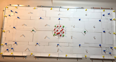
The first step is to create the design.  Since this isn't the first one in the set, I had the previous designs to get me started.  The basic layout is the same as the other transoms so I don't need to worry about picking colors for the glass.  I did need to adjust the dimensions to match the width of the doors (which are different).  In addition to resizing, I changed the designs for the center circles so they were similar to the previous designs, but not identical.  I use SketchUp to create the patterns.  Each piece gets numbered so I can keep track of where it goes throughout the process.  


Pattern for transom over main door


Once the patterns is complete, I print a small copy to be used as a guide and another copy actual size.  This ends up creating multiple pages that must be taped together to make a single pattern.  Once printed and taped together, I use spray adhesive to attach the pattern to poster board.  This makes the pieces substantial enough to be used as guides for cutting and grinding.

I then cut around the outside edge.  I double check the size by measuring and by holding the pattern against the window it will cover and make sure it fits correctly.  I make the pattern slightly smaller than the opening so there will be room to put a metal frame around the finished piece and so there is wiggle room to deal with any expansion/contraction of the wooden window frame.

My working surface is homasote (soundproofing fiberboard) attached to a piece of advantech OSB which sits on top of my work table that has been adjusted to a standing height (thanks to Ikea for the adjustable table legs!).  Homasote makes a good working surface because it is just soft enough that you can use push pins while being firm enough to hold them and not fall apart like cork might.  I cover it with newsprint paper to protect the surface from the flux and solder I will use later.

I place the pattern on the prepared work surface and frame it using angle aluminum pieces that are held to the board by aluminum push pins (Brett drilled small holes in the aluminum for the pins).  This creates a frame that will constrain the size of the finished piece so it will end up the right size when completed.

Aluminum keeper frame in place


Next step is to cut out each individual pattern piece.  To do this I use specially made foil pattern scissors.  They are designed to cut away enough paper to create room for the foil that will be put around each piece of glass before soldering.  

Using the pattern guide I printed, I place the pieces back onto the framed work surface and pin each one in to the correct place.

Pattern cut and pinned into place

The next step is to start cutting the glass. I use a glue stick to attach the pattern piece to the glass and then trace around the outside with the glass cutter to score it.  Then I need to break the glass and hope it breaks along the score line.  I will grind each piece later, so I only need to get the cut close. Extra glass around the outside is fine, but if the glass breaks into the pattern, I start over and cut another piece.  Luckily this pattern has a lot of straight lines as they are much easier to cut than curves are.  I have a special set of pliers that are slightly curved at the end to help with breaking the glass. I use a plastic grid system as a cutting surface which lets the small glass chips fall into the little squares and prevents them from getting in the way.   
Pattern glued to glass

Cut piece


I lay the cut pieces back in the frame.  They won't fit properly until they are all ground to exactly match the pattern.  

Cut pieces awaiting grinding


Once all the pieces are cut, I set up for grinding.  My grinder sits at the end of my work surface.  I use the same grid system under the grinder to catch glass dust, place a screen around the back and sides, as well as a piece of plexiglass to keep any glass from getting in to my eyes.  There is water in the grinder. The process can be pretty messy. 

Grinder and worktable


Each piece gets ground down to the edge of the pattern.  It is a relatively slow process and actually takes longer than the cutting does.  Once all the pieces are ground, they get put back into the frame. There should be enough space around the pieces so that they can move a small amount.  That space will be filled when the pieces are foiled.  

All pieces ground to fit


The paper patterns are then removed from the glass.  To do this I use dish pans filled with very hot water.  The pieces are soaked until the glue has softened enough so the paper comes free.   I set the paper pattern on a paper towel, clean all the glue off the glass with a sponge, and then set the cleaned piece on top of the paper pattern.  This allows me to keep track of which is which.  I then dry the piece with a paper towel and place it back into the frame in its proper place.  The pattern piece is then discarded.  This is a fun part of the process as it is the first time I can really see the colors and pattern emerge.  

Glass cut, patterns removed,  but not yet foiled


I then number each piece with a sharpie so I can keep track of where they belong as I remove them from the frame and begin to foil.  The foil I am using has a black backing.  This is because I will be using a black patina on the solder once the window is complete.  You will be able see the back of the foil, especially around any clear glass pieces, and it looks much better if it all matches.  The different glass varies in thickness so I use a variety of widths to try and keep the foil on the front and back as consistent as possible.   The foil has an adhesive backing that allows it to stick to the glass.  The foil is centered on the edge of the glass and then folded around on each side.  The goal is to have the folded portion the same thickness on each side of the glass.

Aligning the foil


Wrapping the foil around the edge

After applying the foil, it is burnished with something smooth (like the barrel of a pen) to make sure it adheres well and there are no air bubbles or wrinkles.  Most pieces are foiled all the way around, but the outer edges do not need foil as they will be covered by the zinc frame.

Burnishing the foil


Piece completely foiled
This is an edge piece so it only gets foiled on three sides.


Once all the pieces are foiled, they are placed back into the frame.  It is then ready to start soldering.

Foiling complete

Center foiled


Soldering is done by first applying flux to all the seams.  I use a gel flux and apply a very small amount using an acid brush.  Using 60/40 solder and a hot soldering iron I start by soldering anchor points to ensure pieces stay aligned properly.  Solder lines should be rounded as flat lines are weaker.   I work in one area and then move to another to prevent the glass from getting too hot which can cause it to crack.  Once all the seams are soldered, I examine all the lines and fix any flat seams, bubbles or bumps.  I then clean the entire surface with soapy water and rinse.  This prevents from the flux from damaging stuff.  The piece then needs to cool completely.

First side soldered


Once the first side is clean and cooled off, it is then time to turn the piece over and solder the other side.  This is a bit tricky as with only one side soldered, the seams are pretty weak.  For a piece this size you really need a helper.  I start by removing the aluminum frame from the top and sides.  Then holding the piece against the board, stand the board up with the piece resting on the bottom edge.  One person needs to pick the piece up from the top, keeping it vertical the entire time and having their hands spread equally to both sides.  The other person then lowers the board horizontal and the glass is handed to them while standing face to face.  The board is then raised to vertical and the glass is place on the bottom keeper edge again and the entire thing is lowered to horizontal once again.  

The process of flux and soldering is repeated on the second side although there is no need for anchor points as the solder from the other side holds everything in place.  Once the solder is complete, the piece cleaned and cooled, it needs to be turned over once again using the same process described above.  Having both sides soldered makes it stronger, but if the piece is flexed it can break.

Once the first side is facing up again, it is time to add the frame.  I use a zinc came which has a channel for the glass.  I cut 45° corners just like you would when making a wooden picture frame.  Once the zinc is cut, the frame is put around the glass and pinned to hold it in place.  Add flux to the corners and to each seam that touches the frame.  Solder is melted on the corners so it can seep down into the joint and a small bead of solder is run along each seam up to the frame.  The piece is then cleaned and turned over so the frame can be soldered on the reverse side.  Once the frame is in place it is much stronger and can be carefully turned over without needing help from any one else.  It still needs to be carried vertically, as holding it horizontally could put enough stress on it to cause some of the glass to crack.

Zinc frame installed


The piece is essentially done at this point if you want to leave the solder lines silver.  In my case, I want them to be black, so I need to apply a patina.  A patina essentially accelerates the process of oxidation that would happen naturally over time.    

Patina partially applied


Patina complete

The only thing remaining is to install the stained glass into the transom.  It is set in place and kept there by wooden strips screwed in to the window frame.


Brett installing wooden keeper strips


It is done!


Now I need to make the one for the other door and the dining room will be complete!


Thursday, June 24, 2021

Truck Camper Electrical System Upgrade


This entire project started because the AGM batteries in our 2014 Arctic Fox 1150 were 7 years old and were getting pretty tired.  We decided to switch to lithium batteries and discovered that neither the Zamp solar controller or the Progressive Converter/Charger we had would support lithium.  Since we needed to replace them, we decided to go a step further and install an inverter/charger to provide 120V power without being plugged in or running a generator.  We also wanted to be able to keep the batteries charged without having to carry a generator.  That resulted in upgrading to an MPPT solar controller and the addition of a DC/DC charger to the system which will connect to a heavier 2 AWG wire running from the truck alternator via an SB175 Anderson Connector.

Victron Multiplus
12V 2000 watt inverter/charger

Once we made the decision to upgrade and add all these components, we started by tracing the existing wiring. We had previously removed the plywood from the bottom of the camper and having access to the underside made this, not easy, but at least easier than it could have been. 

After learning the existing wiring, we were able to determine what wire we could remove and what wire to leave as it could be reused in the new system.  The next step was to decide on which components to purchase and to figure out where they would all get installed.  We ended up with Battleborn heated batteries and Victron components: a Multiplus Compact 12/2000 watt inverter; a VE-Bus Smart Dongle (provides Bluetooth for the inverter); a SmartSolar MPPT 100/30 solar controller; an Orion-TR Smart 12/12V 30A isolated DC/DC charger; a BMV-712 battery monitor; a Lynx Distributor; two 250A BlueSea bus bars; a BlueSea PowerPost; and 3 BlueSea Maxi fuse blocks.  Selecting the components was fairly easy - finding a spot to put them was significantly more challenging.  

The battery box in our TC would fit 2 of the Battleborns, but since we were adding an inverter, we knew we would be using more power and wanted to add an additional battery.  We do not have an onboard generator, so the generator compartment became the new battery box.   In order to make room for everything, we stripped almost everything out of the generator compartment.  That meant removing the 120V wiring and connection box, the 2 AWG DC wiring that ran to the old battery compartment, and the gas line that ran down to the gas outlet under the bumper (which we had never used).

Wiring and gas line
before removal


Generator compartment with contents removed


The inverter was probably the most challenging to find a spot for since it was the largest component.  We decided to install it where the sliding tray used to be.  We had removed the tray several years ago because it jammed every time we used it despite many attempts to fix it.  With the bottom off the camper, we were able to remove the track for the tray as well.  We cut a board to fit the bottom of the compartment that provided a level surface and a solid attachment spot for the inverter.

Sliding tray and track removed
New support board installed

The remainder of the components were installed in the front of the camper.  We removed the old charger/converter from under the step to the bed and the 6 AWG wire that was connected to it.  We removed the transfer switch from under the kitchen sink being careful to label the wires as we disconnected them so we would know what was what later.  We also removed the Zamp solar controller and connected the input to the output wires so they were long enough to reach the new controller.

Under step to bed with original converter/charger


Once we were sure we had the space to install all the components we wanted, we worked with Battleborn to properly design how everything needed to go together.  They were very responsive in reviewing our proposed design and helping us determine what gauge wire was needed and where fuses should be installed.  They were great about answering any questions we had as we went through the install.  We made a few tweaks as we went along and ended up with a system that looks like this:


Once we had everything, it was time to start installing the components.  The battery disconnect switch, the shunt for the Victron BMV712 battery monitor, and the Victron Lynx Distributor were attached to the rear wall of the old generator compartment (the new battery compartment). We mounted a piece of 3/4" plywood along the back to give the components something solid to attach to.  We also made a board to sit under the batteries that would help hold them in position and provide a place to strap them down.  We found the bottom of the generator compartment was quite thin so we decided to use caulk to glue the board down rather than relying on screws alone. We cut some additional holes though the left hand wall to allow us to run cables to the inverter and forward to the rest of the components. 

Components installed in generator compartment

Battery board with footman loops installed
Battery straps fitted and installed


The new solar controller was installed under the kitchen sink immediately below the controller for the Reico-Titan jacks.  Just below the solar controller we put an electrical connection box where we added new wire to the shore power and the AC fuse panel wires that used to run to the transfer switch.  The wire from shore power goes to AC In on the inverter and the wire to the fuse panel comes from AC Out.


The DC/DC charger was installed under the step to the bed in the spot that used to hold the converter/charger.  Like we did in the generator compartment, we mounted a piece of 3/4" plywood along the front wall under the step.  We attached the positive and negative bus bars as well as the fuse blocks to the plywood.

Components installed under step

Once we had the components in place, we were able to cut the wires and crimp on the lugs.  The wires running from the batteries to the Lynx Distributor and from the Lynx to the inverter are 2/0.

Inverter Installed
We put cable sleeves around the cables to protect
them from the edge of the inverter case.

Battery installation completed


The wires running from the Lynx Distributor forward to the front bus bars are the 2 AWG cables that previously ran from the generator compartment to the old battery box.  The input wires for the solar controller are the original 10 AWG from Northwood, the outputs to the bus bars are new 6 AWG.  The existing 6 AWG wires that previously ran from the batteries are now connected to the front bus bars and supply power to the DC fuse panel.  

Wiring under step completed


For input to the DC/DC controller, we ran 2 AWG out under the kitchen counter (between the old battery box and the water heater) to an Anderson connector on the front edge of the camper.  We found that the max wire size for the DC/DC charger is 6 AWG.  Since we wanted to run 2 AWG out to the Anderson connector, we added a Power Post that we used to connect the black 2 AWG and a short segment of 6 AWG to connect to the charger.  The red wire ran through a fuse block so we were able to convert from 2 AWG to 6 AWG that way.  The output from the DC/DC charger to the bus bars is new 6 AWG.

Wire run out between the battery
box (on left)and the water heater

Wire gable for 2 AWG wires 


Front view of Anderson connector  
The thing hanging down is a dust cover


We installed the BMV 712 Battery Monitor in the side of the kitchen sink cabinet along with the switch for the battery heaters.  The Battleborn heated batteries have a temp control that will only turn on the heater if the internal battery temperature reaches 35F.  However they also provide a switch which allows us to turn off the heat feature completely when we are traveling in the summer.


New wooden cover for location of the old solar controller


For those considering tackling a project like this on your own, one thing to think about is whether you have the necessary tools.  We thought we were fairly well equipped, but found that there were several tools needed that we did not have. Who knew there were so many different types of crimpers?  

We ended up making a bit of a mistake when purchasing an indent crimper for creating the heavier cables and later realizing that same crimper would not work for crimping the Anderson connectors.  We originally purchased a TH1818 crimper from TEMCo and should have purchased the TH0006 instead as it would have been able to crimp both the cables and the Anderson connectors.  That said, we found the TH1818 indent crimper easier to use, so if you don't need to crimp Anderson connectors, then I would suggest going that route.  We purchased directly from TEMCo.  Their prices were better than Amazon and shipping was free and fairly efficient.

We purchased a crimper and ferrules from Ferrules Direct.  Ferrules made inserting wires into the solar controller and the DC/DC charger so much easier than trying to insert and make a good connection with bare wire.

We also purchased a crimper for MC4 connectors.  Our previous solar controller was from Zamp which required the solar panels to be connected in parallel.  Our new controller is MPPT which does better with the panels connected in series.  We rewired the panels using MC4 connectors so they can easily be changed from series to parallel connections if we ever need to.

The wire, lugs, and Anderson connectors we purchased from Battery Cables USA.  We used their extreme battery cable which is amazingly flexible considering it is dual jacketed.  They ship stuff really quickly and inexpensively ($3.97 flat rate shipping, no matter how much stuff you buy).  

We spent more time designing and planning (and waiting for Fed Ex and UPS) than we did actually installing components.  We have done lots of AC wiring, but did not have much experience with DC wiring, especially with the larger gauge wires needed on a system like this.  We tried to test fit everything before drilling, screwing or cutting.  Overall, I would say that the project went pretty well.  We only made a couple of relatively small mistakes that we were able to fix without too much hassle.  

We have tested the system while sitting in the driveway, and are quite pleased with the way everything is working.  The bluetooth enabled Victron components and the Victron Connect app work very well. It is awesome to be able to monitor and change settings on all the components from our phones.  We are very much looking forward to getting out camping and giving the system a real test.


Saturday, August 29, 2020

Installing a Cold Weather Kit on our Norcold Refrigerator

A couple of years ago we were camping during a cold and snowy weekend.  Overnight lows were in the single digits ºF and we discovered that our refrigerator did not work when the weather was that cold.  After a bit of research we found this was a common enough problem that Norcold makes a cold weather kit to correct it.  I believe this kit is now standard, but that was not the case in our 2014 Arctic Fox 1150.  Since we are mostly stuck at home because of the pandemic, we decided to take this opportunity to order and install the kit.  The kit can be found at Amazon, the model number is 634913.  This kit fits 6, 8, 10, 12, 17, and 18 cu ft gas absorption model refrigerators.


Before we could install the kit, we needed to get access to the back of the refrigerator.  We removed the lower refrigerator vent panel on the outside of the camper and found that we could not access the parts needed without moving the refrigerator forward.  We did not find any information about how to remove a refrigerator from an Arctic Fox TC. That is one of the primary motivations for this blog post.  Since we had to figure it out, we thought it might be helpful to others to know what we did.   

We started by turning off the propane, disconnected from shore power and flipped the red battery disconnect (which is in the rear compartment with the dump tank valves in our 1150).   

We then removed the freezer and refrigerator doors so we would have access to the inside attachment points.  There are two screws at the top of the refrigerator that need to be removed.  First remove the plastic caps and then remove the screws.  


Removing those screws will also release the trim that sits across the top of the freezer.


There are multiple screws at the bottom of the refrigerator that need to be removed.  Remove the two screws across the bottom as well as the lower hinge.  This will allow you to remove the lower trim.


Once the lower trim is removed, there are two additional screws that need to be removed.


Once all the internal screws are removed, it is time to move to the outside of the camper.  

We unplugged the 12 V connections and the AC power cord.  We used a VOM to validate that there was no power to the 12 V wires.


We removed the clamp holding the AC power cord just above the outlet.

Next we disconnected the propane.  We used two wrenches, one to loosen the connection and one to prevent anything else from twisting.


Then we removed the attachment screws.  In ours case there are 5 of them, but it appears to be a bit random, so your mileage may vary.


Note there was sealant around the base of the gas line and on top of each of the attachment screws that we needed to remove.  We also found that the stabilizing clamp at the base of the gas line needed to be loosened as it was pinching the metal on the fridge.   

Once all the attachment points were disconnected, we were able to move the refrigerator forward to give us room to work.  There wasn't a good way to get leverage to move it, but we found that by having one person inside the camper pulling and one outside pushing, we were able to move it enough.

The installation instructions for this cold weather kit are really awful.  We read them over several times before figuring out how to approach it.  My recommendation is to ignore step 3 and the associated diagram as it confused more than it helped. 

The kit contains a blue resistive wire that has adhesive on one side.  It gets attached to the thin refrigerant tube.  There is a section of the tube that runs in a curve horizontally at the top.  The wire gets twisted around that section and then runs along side (but not twisted around) the vertical section below it.  There are two notches along the wired tape.  The instructions were not correct about which notch to use.  It will likely vary by model, so I suggest laying out the wire to see how it will fit before removing the adhesive backing.  We found it easier to remove the backing a bit at a time as we went along, rather than to remove it all at once as directed by the instructions.  


Looking down from above 
Horizontal section from above  


 Horizontal section from below


Once the wire tape was in place, we added wire ties at the ends and at the curved points. We used a few more ties than were supplied with the kit.

The kit includes a temperature sensor which needed to be mounted.  We used a sharpie to mark where the holes needed to be and used a 9/64 bit to drill them.  We then used the spacers and screws provided with the kit to mount it.  


The next step was to connect the heater tape to the 12 volt power supply and ground wires.  The instructions said to cut the 12V supply wires, then solder the heater wire into it.  The problem with that approach is that would hardwire the heater to the 12V power supply and we would not be able to remove the refrigerator without having to cut the wires.  We decided to modify the heater wires by adding a quick connect so that we would be able to disconnect both the heater and refrigerator power should we ever need to remove the fridge in the future.


Once the wires were attached, we were ready to put everything back together.  We pushed the refrigerator back into place.  We decided to reattach all the interior screws first, but I suspect the order doesn't really matter.  We then replaced the 5 outside screws, reconnected the gas line and tightened the screw on the stabilizing clamp, reconnected the 12V power and ground wires, and plugged in the AC power cord and reattached the clamp holding it in place.  We then flipped the battery disconnect switch back, plugged in to shore power and turned the propane back on.  We checked the propane connection behind the fridge for leaks.  Everything was fine, so we ran a test to make sure the fridge still worked.  It was fine on AC power.  The first time we tried it on propane we got an error code, probably because we needed to purge the propane line.  We lit one of the burners on the stove, let it run for a few seconds.  When we tried the fridge again, everything worked correctly.  Before closing up the access panel, we recaulked the attachment screws and the base of the gas line with Dicor sealant.  Now we just need to wait until we are camping in cold weather before we will know whether all this effort was actually worth it.